Rebuilding the Rotax 532 ultralight
aircraft engine.
|
|
UltralightNews Ultralight Aircraft
Advisory:
All ultralight aircraft powered by Rotax 532, 582 and 618 aircraft
engines.
Problem area: Rotary valve shaft and
rotary valve shaft seals.
Incident report: A number of ultralight
pilots have reported failure of the rotary valve shaft and
seals on their liquid cooled Rotax aircraft engines.
First indications of this are
discolouration of the rotary valve oil, found in the rotary
valve tank. The oil changes from its normal colour to a white
milky colour.
Suggestions:
In 1984, Rotax introduced the liquid
cooled engine into it's aircraft engine line, the 532 Rotax
which was later updated to the 582. Both the 532 and 582 uses
a 50/50 mixture of Glycol (antifreeze) and distilled water.
Note: While this is the recommended
mixture - for COLD climates - in warmer climates or seasons -
mixtures of 10% anti freeze to 90% distilled water can be
used. This will aid in lowering coolant temperatures -
anti-freeze is NOT an effective coolant! It is used to prevent
freezing and supply lubrication to the system.
Experience has shown that a mixture
of 10% antifreeze can drop temperatures as much as 30 degrees
versus 50% - in some applications.
Do not use tap water -
garden hose water - water from a water softener, or from a
well!
The chemicals in water will cause corrosion of the internal
metal parts of the engine. Including the rotary valve shaft,
cylinder head, and cylinders.
USE DISTILLED WATER!
The use of any water other than
distilled will cause deposits to form on the rotary valve
shaft, causing seal failure. It can also prevent the
transfer of heat from the cylinder to the water jacket, and
corrosion in the cylinder head can cause lack of sufficient
coolant flow.
However there have been some reported
problems even when operators have been using distilled.
This drove the engineers in Austria nuts for a while because
there were virtually no reported cross shaft leakage problems
in Europe, until someone realized that virtually all
antifreeze in Europe is phosphate/silicate free while the
North America is still using phosphates and silicates in
antifreeze, apparently as some sort of blending agent. Thus
if you are using regular aluminum compatible antifreeze and
distilled water, you may still have a rotary valve shaft
problem. This usually shows up as white residue in the
radiator overflow lines and bottle.
A recommended anti freeze is Havoline
extended life antifreeze it is a silicate free antifreeze. |
|
Rotax 532 in field rotary valve shaft replacement
Carburetor removal / coolant & rotary valve tank draining
Tools Required
Small Phillips screw driver
Blade screw driver
Coolant draining
Drain engine coolant at lowest spot possible, into a clean container.
Carburetor removal
sift still connected use a blade screw driver and remove air
cleaner(s) from carburetors. Then using a Phillips screw driver loosen clamp retaining carburetors to
rubber intake manifolds. With the clamp loose gently pry down and back on carburetor and
it will come free of manifold.
Caution:
Never work on a hot engine! Severe injury can result!\
Warning:
This Procedure is only to be used to replace damaged rotary valve shaft, if brass
gear is damaged engine must be dismantled.
Rotary valve shaft replacement-Draining tank
Tools Required.
-ratchet
-13 mm deep reach socket
-blade screw driver
Shop supplies
Oil drain pan
Before removing the rotary valve tank bracket, it is first necessary to drain the rotary
valve tank. On early model engines it will be necessary to remove the hose connected to
the tank, from the outlet located directly below the carburetors, on an engine
installation where the spark plugs are facing up. To do this take a blade screw driver,
and loosen the hose clamp, then using the screw driver, while exerting pressure gently
remove the hose from the outlet. This will allow the oil to drain from the engine and
rotary valve tank.
On new model engines there will be a drain plug (13mm socket head) located directly below
the water pump housing on the exhaust side of the engine. Removal of the drain plug will
allow the oil to drain from both the tank and engine.
Caution:
Once the rotary valve tank hose, or the drain plug, is removed the rotary valve oil will
spill out.
Rotary valve shaft replacement- .bracket removal
Tools Required
.-10 mm deep reach thin walled socket
-13 mm deep reach socket
-Ratchet
-Blade screw driver
Rotary valve tank bracket removal
Using a 13 mm deep reach socket remove the two top bolts retaining the rotary valve cover
plate to the engine. Loosen but do not remove the two lower bolts.
Using a 10 mm deep reach thin walled socket remove the two 10 mm nuts, flat washers and
lock washers holding the water outlet socket in place. It may be necessary to push gently
over on the rotary valve hose to allow placement of the socket.
With these removed gently tilt the rotary valve plate outward, then using a blade screw
driver loosen off the clamp holding the rotary valve hose to the top engine outlet. With
the hose removed the complete bracket with coils will now come clear of the engine.
To remove the bracket completely, disconnect the two wires running the ignition
suppressor box, and the two leads running to the top of the coils. Next remove the nut
from the back of the bracket Remove two top bolts, lock washers and flat washers.
Push over on hose to allow socket placement.
Loosen but do not remove two bottom bolts.
Rotary valve shaft replacement -bracket removal
With all the wiring removed the plate should be completely free from the engine.
Tools Required
ratchet
13 mm socket
Rotary valve plate, valve, and snap ring removal
To completely remove the rotary valve plate remove the two remaining bolts from the bottom
of the plate. Carefully lift the cover off. Remove the rotary valve, wrap it in cloth, and
store in a safe place
. Be careful not to loose or damage large sealing 0 ring.
Using snap ring pliers remove large snap ring, located in front of rotary valve shaft
seal.
Wrap rotary valve in cloth and store in safe place.
Rotary valve shaft replacement-Water pump housing & impeller removal
Tools Required
10 mm socket
ratchet
screw driver
Procedure.
Located directly below the exhaust manifold is the water pump housing, it is retained by
4, 10 mm socket head self threading bolts, remove these and the housing can be removed.
This will expose the water pump impeller and retaining nut. Remove the 10 mm nut, and flat
washer. Remove the impeller, remove the special serrated washer and flat washer.
Caution:
It may be necessary to gently tap the housing with a plastic hammer to break it free from
the sealing gasket.
Update:
New water pump impellers come with a 4 mm hole drilled in them to help prevent air
pockets, and overheating.
Update:
New water pump housings have two drain holes, located top and bottom for better bleeding
of the cooling system.
Caution:
It is sometimes necessary to apply pressure to the sides of the water pump impeller to
break it free from the shaft.
Rotary valve shaft replacement-Shaft removal.
Tools Required
hammer
extrusion jig (876 612)
Shaft removal.
..Insert the extrusion jig (part # 876 612) onto the water pump end of the rotary valve
shaft, threading it in until it is butts against the end of the shaft. Using a propane
torch heat the rotary valve side of engine. Carefully, and forcefully strike the end of
the jig with a hammer. This will drive the rotary valve shaft out the intake side of the
crankcases.
Caution:
Use extreme Caution when hitting shaft. Make sure the driving force is straight
down onto the shaft end, or damage to the shaft will result.
Screw extrusion jig 876 612 onto end of rotary valve shaft, thread it on until it butts
end of shaft.
Rotary valve shaft replacement-Shaft Disassembly
.Tools Required.
Hands/finger
small screw driver
extrusion jig
hammer/press
half of bearing puller tool
.Procedure
Pressing the gear end of the rotary valve shaft against your body, with your fingers apply
pressure down on the spring holding cup (2), break the circlip (1) free from its retaining
groove on the rotary valve shaft. This will allow removal of the spring (3) gear (4) O
ring (5) and shim (6).
To remove bearing, spacer and shim, install the lower half of a bearing puller in behind
the bearing, supporting the bearing and shaft carefully hit the end of the extrusion jig
protecting the other end of the shaft.
Another Procedure that can be used is a small press. Support the bearing, then
gently press down on the jig protected end of the shaft until the bearing, spacer and shim
come free.
Reassembly -Rotary valve shaft
Tools Required
extrusion jig
hot plate
oil container
hammer
Shop supplies
Loctite 648/271
oil
grease Parts
Rotary valve oil seal
O ring
Compression spring
Procedure.
Apply grease to lubricate the lips of the rotary valve seal. Then install the seal onto the
shaft. Heat a small quantity of your two stroke engine oil to 200 degrees F. Submerge the
rotary valve shaft bearing in the oil for approximately 5 minutes. Install small quantity
of Loctite 648/271 onto shaft where bearing will ride. Using gloves remove the bearing
from the oil and install it on the shaft until it rests against end of shaft cut out.
Install shim. Apply a small quantity of Loctite 648/271 green to the shaft area
immediately in front of the shim, install spacer. Rotate the spacer to distribute the
Loctite evenly. Install shim. Install rubber O ring. Install gear. Install spring.
Install spring holding cup. Using spring holding cup compress spring. Install circlip,
make sure that it seats properly.
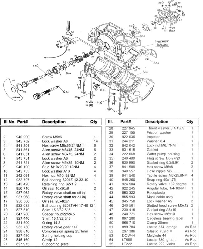
| Rotary valve shaft |
937 969 (with oil
injection) |
| Rotary valve shaft |
937 962 (without oil
injection) |
| Rotary valve seal |
850 710 |
| Rotary valve gear |
935 730 |
| Rotary valve spring |
938 810 |
| Rotary valve circlip |
845 160 |
| Water pump housing gasket
|
831 616 |
|
Reassembly-Rotary valve shaft installation.
Tools Required
hammer
circlip pliers
rotary valve shaft guide sleeve (876 612)
Rotary valve oil seal and support shaft insertion jig (876 602)
outer seal insertion jig (877 050)
inner seal insertion jig (876 512)
Parts required
2 seals
1 rubber washer
1 spacer
1 supporting plate.
Shop supplies
grease
Molykote 111 silicone grease
Procedure
Lubricate the inside of the inner seal with Molykote 111, and using inner seal insertion
jig (876 512), insert the inner seal. Insert the spacer ring making sure that the opening
in the ring is facing the weeper hole. Lubricate the outer seal then using seal insertion
jig (877 050), insert seal into shaft cavity.
Install spacer, rubber washer and supporting plate, use insertion jig to install
supporting plate.
Reassembly-Rotary valve shaft installation.
Procedure
Place rotary valve shaft assembly in freezer for approximately 15 minutes prior to
installation, remove and place rotary valve shaft, with guide sleeve on end into rotary
valve hole, intake side, until bearing rests against crankcase halves. Cover shaft gear
with insertion jig 876 602, Use a propane torch to heat rotary valve side of engine, then
using hammer, sharply strike tool, until shaft is installed. Install circlip, making sure
sharp edge of circlip is facing out.
Install flat washer, serrated washer, water pump impeller, flat washer, apply Loctite 242
then install locking nut. Install gasket, install housing, place blue loctite on self
threading bolts, install the four self threading bolts. For proper torque specifications
refer to section N. For rotary valve timing refer to
Section K Rotary valve timing.
ATTENTION:
Install seals facing direction shown in Fig 80A.
Note if shaft has been damage by the seals REVERSE the seals on
the shaft after cleaning it and you can STILL use the shaft.
Install Molykote 111 into seal cavities
in areas shown, in Fig 80A.
Caution:
Ensure circlip is properly seated into groove in crankcase half.
Caution:
Check locknut to make sure lock is still working. If suspect replace.. |
|
 |
| Have high speed internet & Real Player
installed? Subscribers to the Ultralight Flyer web video magazine
have access to Rotax Engine Rebuilding videos right on the web. |
|
1
2 3 4
5 6 7
8 9 10
11 12 13
14 15 16 Index for this section. |
|
|
|
 |
|
Ultralight Aircraft News Web Magazine .-.-.-. .
No part of this
publication may be copied or distributed, transmitted, transcribed,
stored in a retrieval system, or translated into any human or computer
language, in any form or by any means, electronic, mechanical,
manual, or otherwise, without written permission .
By copying or paraphrasing the intellectual
property on this site, you're automatically signing a binding contract
and agreeing to be billed $10,000 payable immediately. Copyright Ultralight News - Ultralight Flyer.
|
|