Cleaning the Bing 54 carb, is very easy, and checking for wear is
a snap if you know, where and what to look for. But in
most cases pilots will not be servicing the carb(s) because of use
- mainly it will be from lack of use or storage! where and what to look for. But in
most cases pilots will not be servicing the carb(s) because of use
- mainly it will be from lack of use or storage!
In fact if the
engine has been stored improperly it may be necessary to replace
the carb(s) which can be very expensive - or rebuilding them
which is considerably cheaper.
Parts
required:
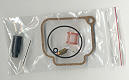
The first thing you'll need to rebuild your carb is a carb rebuild
kit. You'll need one rebuild kit for each carb.
Here is a list of the parts that are included in the carb rebuild
kit:
- Top O Ring- this larger O ring goes under the
top of the carb
 this seals the carb and prevents air from entering and leaning
the mixture out.
this seals the carb and prevents air from entering and leaning
the mixture out.
- Air Screw O Ring- this O ring that seals
the idle air mix screw, and helps lock it in place so it does
not go out of adjustment
- Bowl Gasket- gasket seals the float
bowl to the body of the carb, keeping the fuel in and air out.
- Needle valve - small valve, and
even smaller spring clip which controls the flow of fuel into
the float bowl.
- Hinge Pin - the float arms
ride on this pin, and signs of wear will show up on the pin.
- Sieve Sleeve - this stops foam from entering the main
jet, that is when you pass foam through a screen like this it
turns back into liquid
- Cable Grommet - the grommet prevents water from entering the
top of the carb via the throttle cable and following it down
into the float bowl.
These are the parts that wear over a period of
time, and
need to be replaced. This wear can cause your float bowl to
leak or overflow, provide an improper fuel mixture to your engine,
or allow air or water to enter your carburetor(s).
Main Jets,
Idler jets
While it is possible to clean your main jets, idler jets,
replacement is the better choice if they are badly "gunked up" or
have a lot of hours on them. The jet holes are used to "meter"
fuel into the engine, over time these can become enlarged, with
the passage of fuel through them, giving you a rich mixture. Or if
they have been clogged up they can lean the mixture out. In a
recent test case main jets from a 582 Rotax engine with 368 hours
on it were measured against new - the jets with 368 hours on them
were 4% larger than the new ones. While the low speed or idle jets
were 7% smaller.
Needle jets, jet needles, clips
The needle jets, jet needles, and clips are also an area
of concern. A number of pilots have had accidents when their
engines have failed or lost power in flight when needle/clip have
failed and the needle has dropped down into the main jet blocking
off the fuel. These are replacement items if found to be
worn. If they are the older style they should be updated!
Click
here for update information.
Floats
The floats in the Bing carb have also been updated, with the
new system having two separate floats rather than two floats
joined together on a float arm. The new floats should be examined
for damage around the area where the pin guide goes through the
center of the float. They should also be checked for floatation.
To do this fill you float bowls about 3/4 full and place the
floats on their pins. Allow them to sit for about 30 minutes and
then check to see if they are both level with each other. are both level with each other.
Vent tubes
On older model carbs there were two vent tubes, one coming out
each side of the unit. The latest carbs have one vent tube
connected to the two venting outlets - with breather holes in the
center section of the vent tube.
Apparently in the older style of
venting system air could enter one vent line and exit the other
causing havoc with the float metering system. The new system
prevents this giving a more stable fuel supply.
This new style of
vent can be made from a piece of primer line and putting two side
by side holes in the BOTTOM of the line in the center, these holes
are about 30% of the diameter of the primer line. Too small and
they will not allow the carb to breath properly.
Shop Supplies
Carb cleaner
Rubber gloves
Safety goggles
WD 40 - a great cleaner, that evaporates quickly,
leaves no residue, and can act as a compressor for blowing things
out of the carb passages.
Compressed air
Rags
Tools
Small blade screw driver - comes with Rotax tool kit
Cleaning brush
Small adjustable wrench
Small drift
Hammer
Procedure:
If you have an engine with dual carbs - it is suggested you do one
carb at a time, so that you can use the other for reference if
needed or you can refer to the parts guide.
Click here for tips on remove
the spring, white plastic cup, needle and clip!
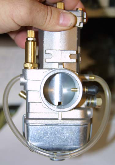
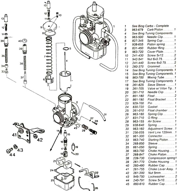
Remove the cover plate (9) and piston assembly (3) from the
carb body. To separate the piston assembly from the cable,
grasp the cover plate in the palm of your left hand, grab the
spring with your extended fingers and compress the spring. Now
with the spring compressed, used the needle to push the spring cup
up, push down on the throttle cable until it is free of the
piston, move it sideways and it will come free of the piston,
release pressure and the unit will come apart. Note the clip
(5) and needle (4) are located BELOW the Spring cup (6).
Inspect the rubber grommet (13) for signs of cracking, A
cracked grommet will allow water to run down the cable into the
float bowl.
Click here for more
information
Inspect the piston for wear in the area where the idle adjustment
screw rides.
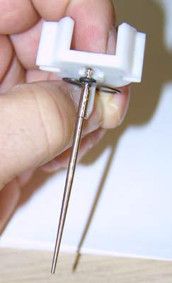
Inspect your needle and clip for wear - check if you have the
updated clip, spring cup and rubber washer.
Click here for more information.
Inspect the rubber sealing ring (8) for damage.
If you have an older carb check to see if the cable has been
wearing on the adjuster screw (12). On older carbs the cover plate
(9) could be put on incorrectly - with the hole offset, which
would damage the throttle cable. New carbs have pins so that the
cover can only be installed one way.
Unscrew the Idle Air Mix Screw and remove the O ring around
the head of the screw.
Next remove the Idle Adjusting screw and spring.
Inspect the screw for wear.
On newer carbs remove the single vent tube, on older carbs remove
the two vent tubes.
To remove the float bowl pry back on the Spring Clip (26) and pry
down on the bowl. In some cases where the engine has been
improperly stored it may be necessary to gently tap the bowl with
a plastic hammer.
Remove the float bowl gasket (24).
Remove the two floats (21).
Remove the Sieve Sleeve (18) from around the main jet post.
Unscrew the Main Jet from the Mixing Tube, Unscrew the
Mixing Tube. Remove the Needle Jet. Located just beside the
main jet is a cavity where the Idle Jet is located unscrew it
(this requires the use of a small screw driver).
Needle valve.
In order to remove the
Needle Valve (19), Needle Clip (20), and Float Bracket (22)
we
first need to remove the Float Arm, we must remove the Hinge Pin that holds the
Float Bracket
in place.
The Hinge Pin is smooth at one end, and knurled at the
other.
The knurled end holds the pin in place. Using a hammer and
small drift,
drive the
pin out from the non knurled end of the pin. A light tap on
the opposite end should dislodge the knurled end of the pin, and
free it.
Once free, slide it out of the carb. With the pin removed,
remove the brass Float Bracket (22), and
then the spring clip and Float Needle (19/20).
Cleaning
At this point we need to clean the parts, using our carburetor
cleaner. Put on your eye protection, and rubber gloves. Take
your float bowl fill it about 1/2 full with cleaner, then put all
of your small metal parts, jets, needle jets, clips, idle jets,
idler screw, float arm etc. in the fluid, and let it sit for about
30 minutes.
While the smaller parts are soaking take the carb body and give
it a thorough cleaning, using a brush and carb cleaner. Once
cleaned used compressed air and blow through all of the orifices.
Then take your can of WD 40 and using the plastic hose that comes
with it spray the WD 40 into all of the holes. When spraying into
the needle valve hole (where #19 goes) and the idler jet hole (14)
spray from the bottom of the carb back INTO the hole. Many times
dirt and debris will lodge itself in the carb body behind the
needle, only to jam up the needle the first time you go to start
the engine. WD 40 tends to move things out of the hole even better
than compressed air. DO NOT use water to rinse the carb out!!
Now take your small parts out and inspect them. Look through
your jets - you should be able to see through the center of them.
On the idler jet there are a number of holes along the bottom side
of the jet, these also should be clear.
If it looks like ANY residue is remaining on the jet(s) - DO
NOT use a wire brush to try to remove it! Replace the jet(s).
With all the parts clean - and or replaced spray them with WD 40
and set them out on a clean rag to dry.
Reassembly:
From your carb rebuild kit retrieve your new Needle Valve.
Place it into the hole in the carb body, then carefully slide the
tiny spring clip on the Needle Valve back onto the
Float bracket needle valve adjustment arm - located in the middle
of the Float Bracket (22).
Holding the Float bracket in place, slide the Hinge Pin back
through the
holes in the body of the carb, and through the hinge openings in
the Float
Bracket. Use your hammer and drift to drive the knurled end of the
Hinge Pin
back into the body of the carb.
Float arm adjustment
Turn the carb upside down on a flat bench. Visually look at the
two float arms they should be level with each other, and parallel to the base of the carb.
If the arms are not level with each other, bend the arms to level
them and then bend the center
tab, as necessary, to make them parallel with the base of the
carb.
Click here for more information
BEFORE you reinstall the Idler Jet, Needle Jet, Mixing Tube, and Main
Jet, verify that they are correct using the
Bing jet chart. In some cases
if your engine was running rough at an idle, or had hot spots at
cruise or when you backed down on power - you may want to change
these jets.
For more information click here.
Slide
the new Sieve Sleeve over the Mixing Tube. Install the new cork
gasket on
the body of the carb, and reinstall the twin Floats onto the pins
in the Float Bowl.
Put the
Bowl back onto the main body of the carb, and secure it with its
spring clip. If your carb does not have the updated vent tubes,
take a short piece of primer line - attach it to the venting
outlets on each side of the carb. Now use pair of wire cutters to
NOTCH the hose a couple of times in the center section directly
below the carb body.
Install the spring onto the Idle Speed Screw, and screw it back
into the
side of the carb. Screw it all the way in and then back it out 3
complete turns. Install the small O ring into the Air
Screw hole and install the Air Screw (28).
GENTLY screw
the
Air Screw back into the body of the carb all the way and then back
it out the recommended turn(s) as per the Bing jet Chart. and install the Air Screw (28).
GENTLY screw
the
Air Screw back into the body of the carb all the way and then back
it out the recommended turn(s) as per the Bing jet Chart.
Click here for the Bing Jet Chart.
Now if you haven't already - update to the new clip, needle, O
ring, and spring cup,
(Click here
for more info) and then reassemble the jet needle, E clip, and tiny O ring that prevents
the jet
needle from spinning inside the E clip. Slide the new rubber
grommet (13)
over the
throttle cable and put the new large O ring on the underside of
the carb cover plate (9). Put the Piston assembly back together,
MAKING SURE THAT THE CLIP AND NEEDLE (4 and 5) ARE BELOW THE SPRING
CUP (6)!
Slide the piston assembly back into the carb body, and screw
down the
lid, on older carbs make sure to turn the cover so that it is
centered on the top of the carb body.
Bing Carburetor Technical Information
Adjusting the Bing Carburetor
The Bing Carburetor (36mm) is a three stage system: Idle,
Midrange, and Top End System. From the moment the engine is
started to approximately 1/4 throttle, the carburetor is running
according to how the idle system is set up. As the idler jet
number decreases, the mixture gets leaner; (see part# 4), as the
number increases, the mixture gets richer. For instance, idler jet
#45 has a leaner mixture than idler Jet #50.
 |
ldler Jets
The Air Regulating Screw (see part# 10) must be set as
stated in the Bing Jet Chart in order to insure smooth
operation of the ldler Jet. This screw adjusts the air/fuel
mixture at idle speeds and for smooth acceleration. Turning
this screw in a clockwise direction creates a richer mixture
while turning it counterclockwise creates a leaner mixture. To
adjust this screw, gently turn in a clockwise direction until
the screw bottoms out, then loosen the screw (in a
counter-clockwise direction) the number of turns as
recommended in the Bing Jet Chart. For example, the ROTAX 503A
would be .5 (1/2 turn) out (effective range 1/2 to 2-1/2 turns
out).
Use the carburetor piston Adjusting Screw (see part# 11)
to adjust the idle RPM. Turn this screw in a counter-clockwise
direction until the Carburetor Piston (see part# 3) is in the
lowest position. Then carefully turn the screw clockwise until
it just engages the piston and then continue to turn it
clockwise for2 to 2-1/2 full turns. This determines the idle
RPM of the engine and should be set at 2,000 RPM.
The Midrange System affects the carburetor for
approximately 1/4 to 3/4 throttle. Once again, the lower the
number of the Needle Jet, the leaner the mixture. |
|

 |
Needle Jets, Jet Needles
(NOTE: Jet needle must always be under plastic spring cup)
The Jet Needle (see part# 2) has grooves which the
Holding Plate (see part# 3) can be snapped onto.
The
grooves are numbered 1. 2, and 3 with number 1 in the top
position (note: some jet needles have 4 grooves as in diagram
#1 at right).
When the Holding Plate (see part# 3); is snapped
onto the top position (#1) of the jet needle, a leaner mixture
is created than if it were mounted in the #2 groove.
- lnstall sieve sleeve by slightly squeezing it by pushing
it all the way up the mixing tube.
- Smaller numbers indicate decreasing jet opening and
leaner conditions.
- The #54 marked on the side of the carb is just a casting
mark.
- Float guide pins should be polished to insure smooth
float action.
- Floats with aluminum guides should be replaced.
- lnspect jet needle grooves for wear every 50 hours.
- Float arm should start out parallel to the float chamber
base.
- Fuel pump must be in system to insure correct fuel
level.
|
How to Check the Float Level
- Start and warm up engine.
- Run the engine at 3/4 power for 2 minutes.
- Let engine idle back and cool down for 1 minute.
- Shut off engine and fuel system (if the fuel system is
an overhead system).
- Remove float bowl.
- Remove the floats from the float bowl while float bowl
is sitting on a level surface.
- The fuel level should measure approximately 1/2" from
the top edge of the float bowl.
Fuel level below 1/2" will cause a lean mixture.
Fuel level above 1/2" will cause a rich mixture. |
Main Jets,
Idler jets
While it is possible to clean your main jets, idler jets,
replacement is the better choice if they are badly "gunked up" or
have a lot of hours on them. The jet holes are used to "meter"
fuel into the engine, over time these can become enlarged, with
the passage of fuel through them, giving you a rich mixture. Or if
they have been clogged up they can lean the mixture out. In a
recent test case main jets from a 582 Rotax engine with 368 hours
on it were measured against new - the jets with 368 hours on them
were 4% larger than the new ones. While the low speed or idle jets
were 7% smaller.
Needle jets, jet needles, clips
The needle jets, jet needles, and clips are also an area
of concern. A number of pilots have had accidents when their
engines have failed or lost power in flight when needle/clip have
failed and the needle has dropped down into the main jet blocking
off the fuel. These are replacement items if found to be
worn. If they are the older style they should be updated!
Click
here for update information.
Floats
The floats in the Bing carb have also been updated, with the
new system having two separate floats rather than two floats
joined together on a float arm. The new floats should be examined
for damage around the area where the pin guide goes through the
center of the float. They should also be checked for floatation.
To do this fill you float bowls about 3/4 full and place the
floats on their pins. Allow them to sit for about 30 minutes and
then check to see if they are both level with each other.
Vent tubes
On older model carbs there were two vent tubes, one coming out
each side of the unit. The latest carbs have one vent tube
connected to the two venting outlets - with breather holes in the
center section of the vent tube.
Apparently in the older style of
venting system air could enter one vent line and exit the other
causing havoc with the float metering system. The new system
prevents this giving a more stable fuel supply.
This new style of
vent can be made from a piece of primer line and putting two side
by side holes in the BOTTOM of the line in the center, these holes
are about 30% of the diameter of the primer line. Too small and
they will not allow the carb to breath properly.
|
|