|
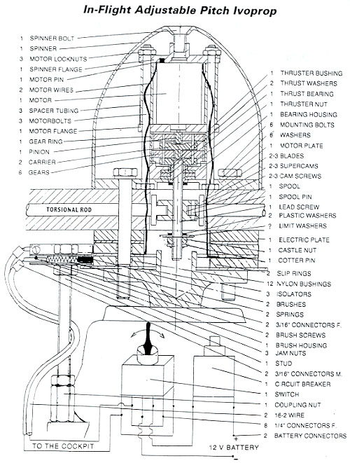
The IVOPROP operates on a COMPLETELY UNIQUE adjustable
pitch system that allows for substantially less hardware and rotating mass
than any other ground pitch adjustable prop. The unique pitch adjustment
design operates on the principle of twisting the blades through the chromoly alloy steel torsional rod cast inside the blade. The outer end of
the torsional rod is firmly anchored inside the outer blade section. The
round torsional rod is capable of rotating inside the blade, except for
the outer end. The hub ends formed into square shape. pitch adjustment
design operates on the principle of twisting the blades through the chromoly alloy steel torsional rod cast inside the blade. The outer end of
the torsional rod is firmly anchored inside the outer blade section. The
round torsional rod is capable of rotating inside the blade, except for
the outer end. The hub ends formed into square shape.
Both models utilize the same carbon / graphite fiber blades
with stainless steel leading edges. The blades are capable of pitch change
3 to 17 degrees on the tips or inches of helix advancement from 18"
to 52".
The ability to change the pitch in flight is as significant
for the airplane pilot as for the driver of a car to shift gears in the
transmission
These results in substantial savings in fuel, engines wear
and noise.
� Pilot
controls the pitch trough the toggle switch mounted in the cockpit.
Pressing the toggle switch one way sends electric current trough the
graphite brushes to the slip rings and finally to the electric motor.
� Depressing
the toggle switch the other way reverses the polarity of current and the
rotation of electric motor. The pitch changes operation is similar to the
power windows in an automobile. As long as you hold the switch in one
direction- the pitch changes in that direction and you observe the result
on your RPM meter.
� Torque
from the electric motor is multiplied in a two-stage planetary gear drive,
which turn the lead screw.
� Lead
screw is supported by a thrust bearing and converts it's rotary motion
into axial movement of the spool. �
The spool is linked to the super cams, which turn the torsional
rods. Torsional rods transmit the movement from the center of the prop to
the outside section of the blade. This causes the blade to twist therefore
changing the pitch in the same manner as the ground adjustable pitch
system. � Total time
required for full range of adjustment is about 5 seconds.
� Movement
of the spool can be restricted each way by inserting washers on the lead
screw. This limits maximum and minimum pitch and prevents engine
over-revving.
� Mounts
directly to any rotax gearbox, "B", "C" models. Can be
adapted to VW, Subaru, Hirth, Arrow, and smaller Lycoming and continental
engines.
� Older
models Ivoprop ground adjustable props can be convert to In-Flight
Adjustable System by means of retrofit kit. Torsional rod must be offset
toward the leading edge of the prop. Early model props with the torsional
rod located in direct center of the blade can not be converted.
� In-Flight
adjustable hub comes assembled with instructions on how to use it.
�
Total weight of 3-blades 72" diameter In-Flight Adjustable
IVOPROP including wire harness, spinner, control switch, mounting
hardware, and the circuit breaker is I Olbs.
Insert the mounting bolt with
the washer through the motor plate in one of the boltholes closest to the
two motor wires.
Insert one blade on the mounting
bolt. Flat airfoil side towards the electric motor for pusher. Curved
airfoil side toward electric motor for tractor.
Rotate the blade so that the
super cam goes into the groove in the spool. Insert second bolt through
the motor plate and blade.
Insert electrical plate (the one
without nylon bushings) on the bolts. Insert small isolator.
Insert slip ring on the bolts.
Do not push out the nylon bushings.
Bend one motor wire in right
angle radially outward on the slip ring. Insert second small isolator.
Bend second motor wire the same
way like the first one on the isolator. Insert second slip ring. Insert
large isolator.
Bolt prop loosely on the flange.
Insert remaining blade (s)
between plates and torque mounting bolts to 200 inch X Lbs.
Rotax reduction. "B ":
replace one of the 8mm nuts on the gearbox closest to the prop axis with a
coupling nut (torque 150inchXLbs.)
Screw the stud into the coupling
nut deep enough to clear the blades, and lock it with jam nut.
Rotax reduction "C ":
replace 6mm bolt on the gearbox with stud and counter torque one of the jam
nuts against the gearbox I 00inch. X Lbs.
Other than Rotax : Mount the
stud "somehow " next to the flange so that brushes will contact
slip rings Screw the jam nut on the stud, insert the brush housing and
screw the last jam nut on the stud
Position and torque the jam nuts
against brush housing so that brush on the blade side is in contact with
brush plate right next to the isolator. That way there is a maximum
clearance between brush housing and the blades.
Install switch and circuit
breaker in the cockpit in a place where you can easy reach but not
accidentally activate.
Attach 3116" connectors to
the brush housing running the wire under the stud
Attach battery connectors to the
battery. Circuit breaker wire belongs to the positive pole.
Write next to the switch
direction of the pitch change. By interchanging brush connectors you can
change the direction of the pitch change.
Example:
Pitch up RPM down Cruise
Pitch down RPM up Climb
* Caution : Brushes are brittle. Do not brake them.
Setting
Your Own Pitch Limits How
To Fly With It
The pitch change operation in
flight can be greatly simplified by restricting movement of the spool
therefore limiting the pitch change from your best climb pitch to your
best cruise pitch. Land with the prop in your best climb pitch.
Take prop off the flange. Do not
take the mounting bolts out of the prop.
Measure (with a calliper) the
distance from the spool and the end of the lead screw and write it down.
Mount the prop back on the flange.
Go flying and find your almost
best cruise pitch. Remember "almost " stands for the pitch which
will still give you a little bit of climb.
Land the prop in your
"almost " best cruise pitch.
Take the prop of the flange and
measure the distance between the spool and the end of the lead screw and
write down.
Mount the prop back on the flange
and bring it to neutral (you can hear it -no load on the electric motor.)
Take prop apart.
Insert limit washers on the lead
screw so that spool can not travel beyond your measurements.
Do not forget to insert plastic
washers on each side of the spool. Failure to do so will immediately lead
to the destruction of the gears in the planetary drive.
Note: the thickness of the
plastic washer under load is about Y2qf its original thickness.
Do the first flight in still air.
Run the prop W. 0. T on the ground and adjust pitch
offew hundred R.P.M. bellow your maximum HP R. P. M (W. 0. P. means wide
open throttle.)
Climb W. 0. T and adjust the pitch to maximum climb
rate. (Do not exceed maximum allowable R.P.M for your power plant.)
Remember your R.P.M at your best climb pitch.
After reaching cruising altitude hold W. 0. T and
start increasing pitch by short impulses until your climb rate is about
200ft/min.
Remember your W. 0. T R.P.M at this your almost
best cruise pitch.
Throttle back until your R. P. M start dropping or
until your climb is zero.
Before landing go for a moment into W. 0. T and
start decreasing the pitch by short pulses until you reach your best climb
R.P.M which you remember from the take-off
Do not change the pitch after landing. Run the prop
W. 0. T on the ground and remember your best climb R. P. M which you remember from
the take off
Before next take-off run prop W. 0. T and read your
best climb ground R.P.M to make sure that your pitch is in climb setting.
Next time you want to cruise even in a turbulent air just
use your almost best cruise R. P. M which you remember from your last flight
in order to put prop in your almost best cruise
Important:
Assume
that in-flight pitch adjustment can quit on you any time in which case the
pitch stays where it is. Therefore do not pitch prop up for cruise more
than you need to slightly climb. So you can bring your plane back where
you came from.
Do not
use pitch adjustment more than you need and always allow some time for
electrical components to cool down between cycles.
Do not
run the prop without the circuit breaker, which is supplied with it.
If you
hold the switch for few seconds after reaching the pitch limit therefore
stalling the motor the circuit breaker pops out and you have to wait
several seconds to reset it.
The
system will not run safely on regulated DC current from regular there you
need a battery. Before disassembling the prop always bring the pitch to
the neutral
Never
engage pitch adjustment only on one blade or on two blades spaced 120
degrees. Do not remove carbon deposit from brushes on slip rings.
Do not
rely on spring, which returns the switch lever to the neutral position.
If you
can not change the pitch in-flight try it in idle R. P. M or try to move
the Switch lever back and forth.
Do not
copy terrene in cruise pitch.
Even if you fly
without setting your pitch limits you still need one limit washer the
castle nut and the plastic washer.
Do not
shorten the 12'wires or circuit breaker will pop out sooner. Keep the
grease away from plastic and limit washers.
Brushes
wear much faster when wet. Therefore if you really have to fly in a rain
pitch the prop for climb, loosen the jam nut, which is against coupling
nut, turn brush housing away from brush plates and retorque the jam nut.
Make
sure that there is no electric continuity between brush and plates and the
engine frame-otherwise you could destroy your regulator-rectifier when
changing the pitch while engine is running.
After
you are done with setting the limits and the final installation seal the
gaps between the blades with silicon and install the spinner to keep the
water and dust from getting into the mechanism. Tie down or put the tape
over the brush connectors so they will not come loose in flight.
Apply
blue loctite on the spinner bolt and bolt and torque to 35 inch XLbs.
otherwise your spinner will fall off
If you
wish to secure mounting bolts- use 8mm nylon lock nuts (not supplied) on
the other side of the flange.
Use
only the hardware supplied with the prop, never drill or modify the
boltholes in the blade (s). Maintain the 200-inch XLbs. torque on the
bolts.
Make
sure that there is at least 5" of clearance between the blade
tips and trailing edge of the wing, radiator rudder, or whatever, because
the blades are design to flex-x back and forth more than wooden blades. Do
not slide your fingers along the trailing or leading edge of the blade, fibbers
may pierce your skin.
If you
wish to increase top speed or decrease cruise R.P.M., switch to a 2-blade
prop or cut the 3-blade prop to a smaller diameter using a hack saw, as
long as you cut the same length piece from each blade, the prop will
remain in balance. Do not cut the prop to less than 48" diameter.
When switching from
3-blade to a 2-blade configuration, increase the pitch about 4 degrees.
Rotax
engines develop maximum horsepower around 6500 RPM so pitch the prop
accordingly.
If you
are going to use other than skull cap type spinner make sure that there is
at least 114 " clearance between blades and cut-outs in the spinner.
If your
aircraft holds U.S. experimental airworthiness certificate you are
supposed to contact the F.A.A. FSDO before flying the aircraft. When notified,
the F.A.A. inspector can determine if procedure was major change (as
defined per far 21.93 and listed in appendix a to part 43) and if any
additional inspections or operating limitations are needed prior the flight. |