|
A quick inspection reveals that he can not turn the
engine over, it has locked up. He removes the engine, and takes it
to his local Rotax ultralight aircraft engine repair station.
Upon disassembly it is found that the gear box ring
halves (22) have shattered, the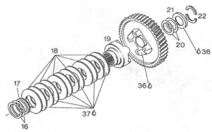 angular retaining ring (21) has been
damaged and the groove on the prop shaft that the ring halves fit
into has been damaged. angular retaining ring (21) has been
damaged and the groove on the prop shaft that the ring halves fit
into has been damaged.
Further inspection reveals that the spring washers
(18), are worn badly on the edges and at the center. The service
center decides to reassemble the gear box to check for gear box
preload.
To get the proper preload a number of shims had to be
added.
The improper preload was allowing the springs to
compress and decompress. This was putting a "hammering" action on
the retaining ring and ring halves, pounding the halves against the
prop shaft groove, until they failed.
Suggestions:
If you are flying on a Rotax A or B gear box it is
suggested that at 150 hours and at engine rebuild 300 hours the gear
box be inspected and the proper preload on the spring washers be
set.
*Checking and adjusting of gearbox, preload of
springs (A/B- type gearbox)
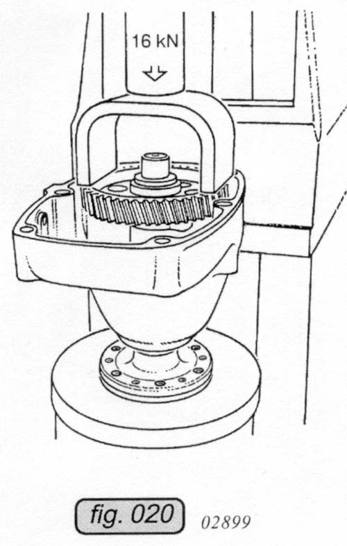
- Place gear box on a suitable support under hand
press.
- Place the mounting yoke, part no. 876 880 on
the dog gear (20).
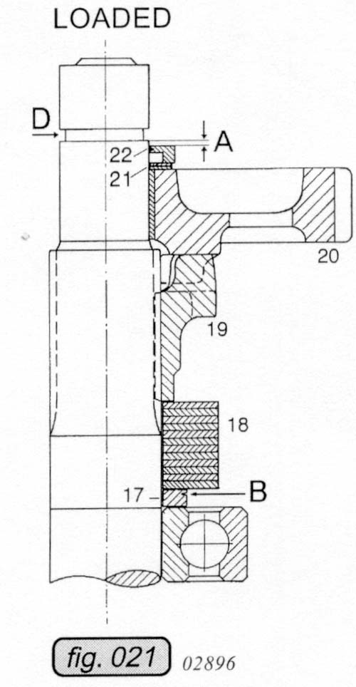
- Place angular ring (22 fig 021) upside down
(with "L" shape down- wards (see ill. fig 021) on prop shaft to
facilitate reading of the distance A.
- Apply a load of 16 kN (3600 lbs fig 020) on the
dog gear via the mounting yoke. With this load, disk springs will
be completely compressed.
ATTENTION: Do not exceed maximum load of 16 kN
(3600 lbs), otherwise cover or dog gear will be damaged.
With springs in compressed state, measure A, the distance from top
side of angular ring to lower edge of groove (see illustration).
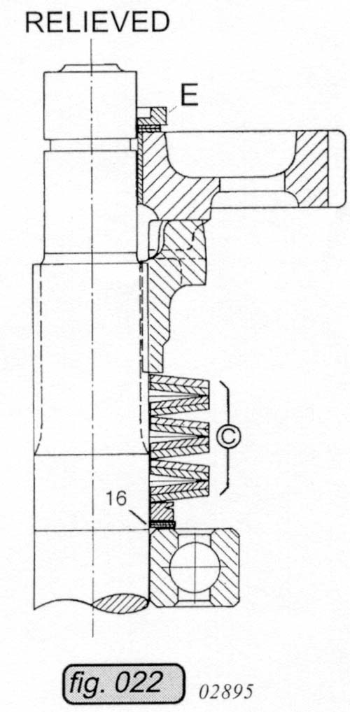
Relieve pressure, remove all items from prop shaft and compensate
distance A, by placing appropriate shims (16 fig 022) under distance
ring (17 fig 021).
Shims are available as spare parts in the sizes 0.1 / 0.2 / 0.3 /
0.5 and 1.0 mm.
|