|
VENTILATING SYSTEM FOR CHALLENGER A BIT OF
THEORY |
|
 |
 |
|
WINTER |
SUMMER |
In winter, warm air is pushed
through cylinder cowl, into the fabric duct, then redirected by
the baffle into the heater box and down into the 4 inch aluminum
duct in the cabin.
In summer, fresh air flows into the air scoop and is redirected by
the baffle into the 4 inch round aluminum duct in the cabin.
|
|
 |
 |
|
WINTER TOO WARM |
SUMMER TOO COLD |
| In winter, when the cabin gets too
hot or in summer when the cabin gets to cold, a push pull control
cable moves the baffle to expel the air out. |
|
THE CHALLENGER SYSTEM |
| This system is based on the
standard heat box used before on air-cooled motor airplanes. |
|
OPERATION |
| Warm air is pushed out of the
cylinder cowl and transferred via a fabric duct to a control box.
From this box, via a remotely controlled baffle, air is directed
inside through a conduit or expelled outside. The fabric duct is
interchangeable with an air scoop. Fresh ram air caught by this
scoop is sent to the box and controlled the same way as described
before. |
|
COMPARISON |
Heaters that are attached to the
motor all have the same problem vibration! It's just a matter of
time. Our heater box sits on the two lower curved ribs under the
motor, considerably reducing the vibration. Test have shown our
heater box will survive many years before it needs servicing.
Many Challenger owners had to lower the top rib
to be able to install their heater box on the motor. This
modification alters the air flow very close to the propeller and
could add turbulence in this area, producing more vibrations and
slightly reducing the prop's efficiency.
With our system, the fabric duct uses the resilient space between
the top rib and cylinder cowl, entirely closing this gap. Many
Challenger owners had complained about the fact they had to remove
the heater box from the cowling to service the plugs.
With our system, removal of the fabric duct is easy since it's
attached to the cowling with Velcro.
By covering the cylinder cowl, warm air outlet and spark plug
area, the system collects all the warm air that's possible to
retrieve from the motor. In our test, at -10� F, we were able to
keep inside temperature to 50�F, quite comfortable. |
| |
|
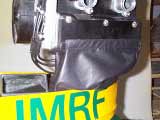
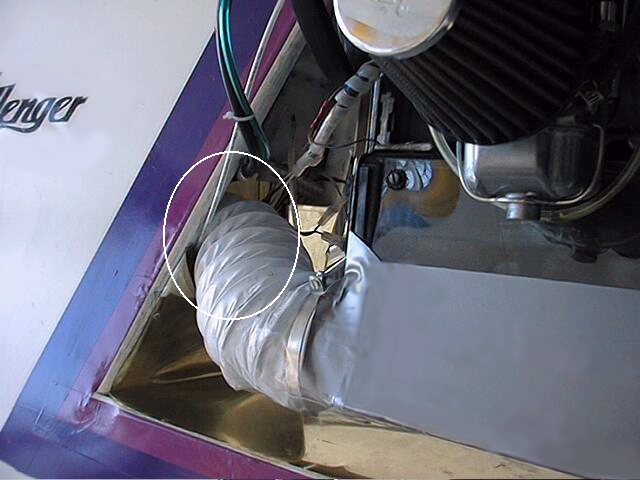
THE FABRIC DUCT
Made of oil, UV and cold crack resistant fabric, the duct is
resistant to all weather.
It is also very easy to clean. Velcro at both
ends simplify its installation. |
THE AIR SCOOP
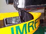
Made with the same fabric, the scoop is solidly attached to the
heater box rendering it impossible to be thrown into the prop. |
|
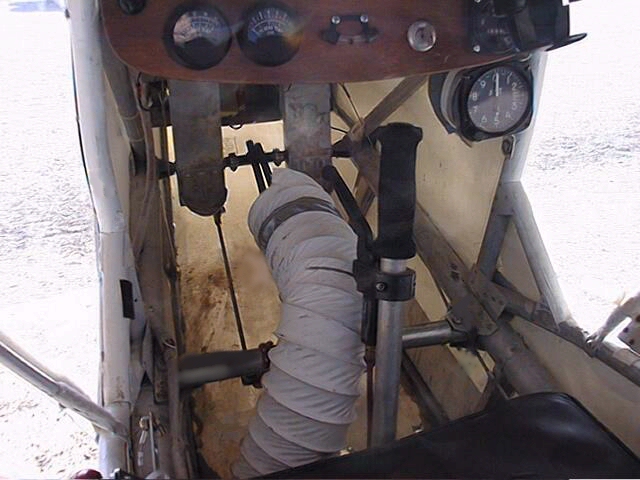
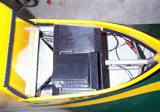
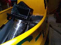
THE HEATER BOX |
Made from
composite, the heater box is light and rugged. The box sits on a
base to permit its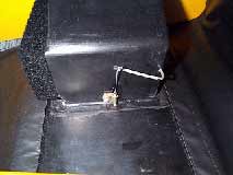 installation directly on the lower curved ribs. Again, Velcro is
used to attach the base to the ribs.
installation directly on the lower curved ribs. Again, Velcro is
used to attach the base to the ribs.
A 4 inch flange, under the base, accepts 4 inch
aluminum tubing, with solid tubing preferred. Inside, a fabric
controlled baffle directs air out of or into the cabin via the
base flange.
The control arm and baffle frame are from
galvanized steel. The heater box can be painted with your color
choice. The complete heater box assembly weighs just under a
pound. |
| |
|
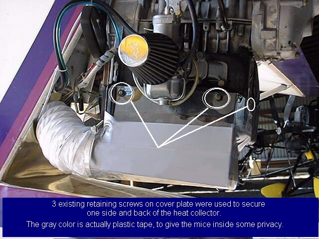
COVERS
To complete winterization, the under motor and firewall areas have
to
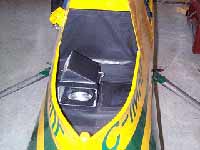 be
totally closed. If not properly closed, warm air will be sucked
out rendering it impossible to heat up the cabin. be
totally closed. If not properly closed, warm air will be sucked
out rendering it impossible to heat up the cabin.
We supply two covers with every kit, one for the
rear section and one to cover front part and the firewall section.
(For now these covers are adjusted to fit the
new Challenger version.) |
| |
|
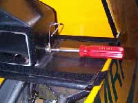
CONTROL CABLE
The control cable is a push pull type. Its length, 156 inches is
more than enough to install the control knob at a convenient
location of your choice. |
| |
HARDWARE SUPPLIED
Except for the aluminum tubing, everything needed is included. The
tube can be easily bought locally for a price lower than its
shipping cost. |
| |
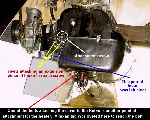
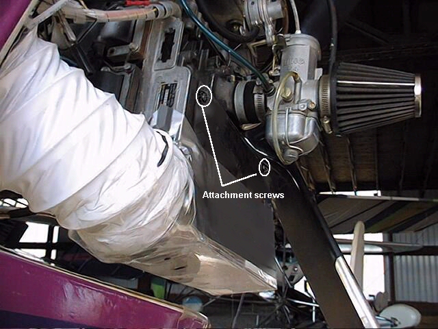
INSTALLATION
To make it easy to install, even with the motor installed,
self-adhesive Velcro is used. The only important task is to clean
all areas before attaching any Velcro.
The box is also clamped to the aluminum tube and
control cable rendering it impossible to fly into the prop. All
Velcro attached to the cylinder cowl is secured with pop rivets at
both ends.
Instructions are complete including several drawings.
|
|
NOTE |
Our heater box has been installed
and tested on our plane for 5 years now (over 350 hrs) and has
never needed servicing. It is a cool idea in summer and a warm
experience in winter.
|
|
MODEL: |
HBK1 for CHALLENGER I $295.00 |
|
| |
HBK2 for CHALLENGER II $295.00 |
|
| |
|
| |