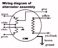
For alternator wiring
diagram refer to Fig (1).
As mentioned the output is
in AC voltage (alternating voltage) and has to be converted to DC
(direct current) so that we can run our strobe lights, radios etc.
To do this we can use a shunt style regulator. The word "shunt"
means that the system moves or shunts "excess power" to a
ground when the voltages output is more than it is suppose to be,
thus giving us a constant 13.6 volts.
When a load or a "consumer"
is put into the system such as an auxiliary fuel pump, radio, strobe
lights, or heater the regulator does not have to "shunt" as much
power to ground. In a lightly loaded situation, or where the engine
is running with no load the regulator - rectifier will get very hot
and thus should be mounted in an air stream and away from fuel
lines, wiring etc. and must have a CLEAN solid ground.
This type of system does
work well and usually doesn't give us any problems. If there is a
problem it will show up in your volt meter readings in either a drop
in voltage or an overcharging situation.
Troubleshooting a Rotax
Ducati electrical system.
The first thing to check in
troubleshooting the system is the battery for good condition and
FLUID level. If it is low then refill it with DISTILLED water to the
proper level. DO NOT use tap water or any other water any minerals
in the water will cause a reaction inside the battery!
A good battery should test
out at 12.6 to 12.7 volts DC when the engine is not running. That
means if you turn the main power on your voltmeter should be reading
12.6 to 12.7 volts. When running this will then go up to 13.8 to
14.5 volts DC. Anything below or above these values is not good.
A system running constantly
above over 14 volts will cause overcharging and "boiling" of the
battery requiring constant refilling. This higher than normal
voltage can damaged a battery and other electronic components such
as radios and strobes.
If the "charging coils"
or stator unit is thought to be the problem disconnect the regulator
rectifier and do a voltage check
Normal Volts AC readings are:
16 volts VAC at 1300 RPM,
27 VAC at 2200 RPM
50 VAC at 4000 RPM
77 VAC at 6400 RPM
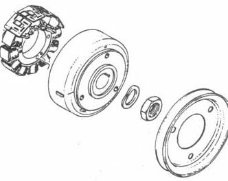
It is not often that a
stator unit will fail, unless you have damaged it by improperly
installing bolts that are too long into the electric start or fan
pulley, or inadvertently connecting 12 VDC directly to it while
boosting your battery. This can be checked easily with a volt meter
you are looking for a shorted windings or a ground.
Next check the wiring
connections where they connect to the regulator. If either is
corroded or not making a connection the system will not work.
Next check the GROUND
connection for the regulator-rectifier. If you have a poor ground or
NO ground the rectifier will not work.
Wiring Diagrams
Rotax supplies two different regulators, the
one RECOMMENDED for use with the Ducati ignition is 264 870.
It has a series of fins which aid in dissipating the heat generated
by the regulator.
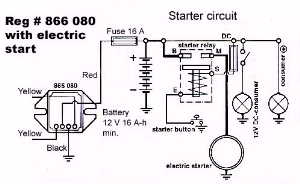
The 866 080 is used with the
early model point ignition engines which have a lower output than
the Ducati ignition engines. The 866 080 also requires a 1 amp
"consumer" to prevent excessive AC voltage from reaching the
regulator
This section consists of six wiring diagrams taken from the
Rotax manual that show how a given voltage regulator is wired into a given
electrical system.
In this sequence of diagrams note the on the
Ducati ignition engines the yellow/black wires coming from the
stator connect to the two yellow wires on the regulator.


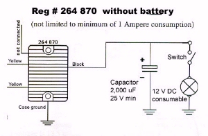
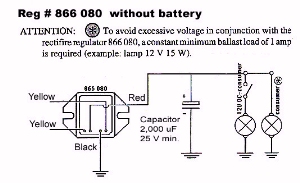 Regulator
866 080 without a battery
Regulator
866 080 without a battery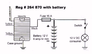 Regulator # 264 870
with a battery.
Regulator # 264 870
with a battery.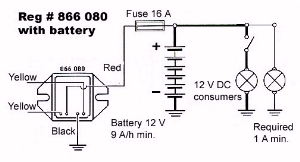 Regulator # 866 080
with a battery.
Regulator # 866 080
with a battery.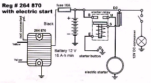 Regulator
264 870 using a battery and electric start
Regulator
264 870 using a battery and electric start