Rotax 582 exhaust gas probe location, Rotax EGT probe location. |
||
|
||
|
|
|

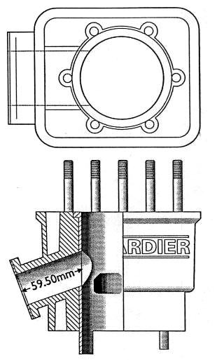
Rotax Exhaust Gas Probe Positions
|
|
|
The manual description of where to drill the EGT probe holes is vague to say the least. The result is that in a lot of circumstances the readings tend to be on the high side even though the engine running condition is correct. Rotax simply define the location of the sensor's probe
as being 100 mm from the piston
The first illustration shows the distance from the piston skirt to the manifold mounting face including the compressed gasket which is 59.50mm for a 582 engine. The remaining 41.50mm is within the manifold itself so therefore the positioning of the probe hole is important to ensure reliable indications. Too far downstream of the correct location will result in higher readings and likewise too close to the piston will yield lower readings. Think of it in terms of a welders gas flame where the hottest part just beyond the blue tip and the coolest inside the cone. Lay the manifold so that the welded flange is parallel to the work surface. Cut two pieces of thin aluminium cut to the dimensions of the flange faces and mark their exact centers in each plane. Tape these to each mounting flange. Mark a line on each of the manifold branches exactly 38.00mm back toward the ball junction and parallel to the welded flanges. Next mark a line exactly half way across each of the branches. Where the lines intersect is the positions of the probe tips. Because the flange faces are welded onto the branches at an angle the position will be different dependent on which face the probes will be mounted. It is important to remember therefore that the spots indicate where the tip should lie and it will be necessary to place packing washers under the mounting bands to adjust the insertion of each probe. If the tips lie closer to one wall then again there will be errors in readings. The manifold is now predrilled and has two threaded bosses to accept the probes which eliminates entirely the problem but the 582 manifold is shared by other engine types and therefore it is up to the installer to position the probes correctly. After the band clips have been formed and tightened then wrap a length of safety wire over the bands just in case they break allowing the probe to exit the holes from vibration. Finally because the probes are hot junction types ensure the braided cables are kept out of direct airflow and are not secured to "cold" attachments because again readings will be affected. Where it is necessary to to make an attachment to a cold surface insulate the cables with plastic sleeving. Graham Laught, UKAvid |
|
|
 |
|
|
| Return to Main Index for this section |
|
|
| Ultralight Aircraft News Web Magazine EMAIL for l Information. No part of this publication may be copied or distributed, transmitted, transcribed, stored in a retrieval system, or translated into any human or computer language, in any form or by any means, electronic, mechanical, manual, or otherwise, without written permission of Ultralight Aircraft News. By copying or paraphrasing the intellectual property on this site, you're automatically signing a binding contract and agreeing to be billed $10,000 payable immediately. Copyright Ultralight News EMAIL |
 skirt
which is fine so long as you can relate that information to the exhaust
tract as a whole.
skirt
which is fine so long as you can relate that information to the exhaust
tract as a whole.